Single Design Panelizer
Quickly transform your PCB design into an X by Y array ready for PCB assembly.

Available With:

ViewMate Professional
Viewmate Professional Html

CAMMaster Designer
New for Designers and Engineers! Advanced design features at your fingertips.

CAMMaster
PentaLogix's most complete CAM software designed to meet tomorrow's manufacturing needs.
For more information, please email us at support@pentalogix.com
Preparing an Array for Assembly is a Seven Step Process:
Step 1 - Load PCB Design Data
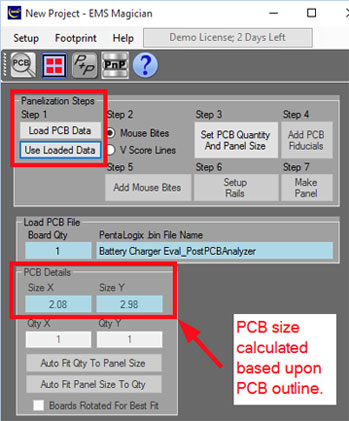
If you already have your PCB design files loaded in the CAM editor, then simply click on "Use Loaded Data" button. If you want to start with new data, then click on the "Load PCB Data" button. In either case, the Single Design Panelizer will display the size of your PCB:
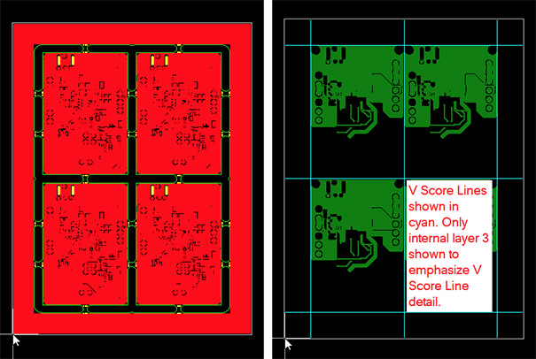
Step 2 - Choose "Mouse Bites" or "V Score Lines" Option
You can choose to use tab routs with "Mouse Bites" or "V Score Lines" to depanel your PCB. Each of these is shown below. Tab routs with "Mouse Bites" are shown on the left. V Score Lines are shown on the right. To depanel an array using "Mouse Bites", we suggest that you consider using a Dremel tool with a sanding disk. This makes it very easy to cut through the "Mouse Bites" using the edge of the disk. Then, use the face of the disk to smooth out any remaining rough spots caused by the mouse bites. With V Score Lines, you simply snap the boards apart after assembly. Depaneling with mouse bites gives a cleaner board edge. V Score Line depaneling is simpler, but results in a rougher board edge. Also, V Score Line depaneling is only really suitable for square or rectangular boards.
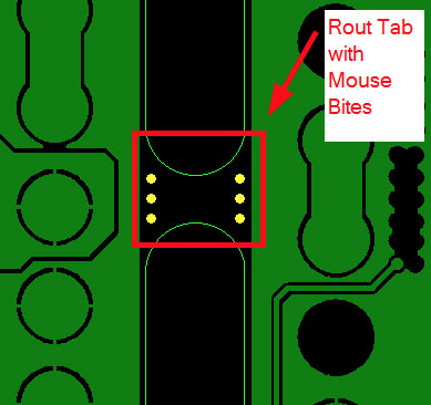
"Mouse Bite" details are shown in the figure below:
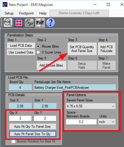
Step 3 - Set PCB Quantity and Panel Size
Click on the "Set PCB Quantity And Panel Size" button. Then proceed in one of two ways:
Enter the desired quantity of boards in X and Y and choose your desired panel size. Click on the "Auto Fit Qty To Panel Size" button. The Single Design Panelizer will calculate the needed panel size and add it to the "Saved Panel Sizes" combo box.
Select a previously saved panel size from the "Saved Panel Sizes" combo box. Click on "Auto Fit Qty to Panel Size" and the Single Design Panelizer will determine how many boards will fit in the X and Y axis on your chosen panel size. Note that both "Normal" and "Rotated" fits will be calculated. If more boards fit in the rotated position, then the "Boards Rotated For Best Fit" check box will be checked.
Step 4 - Add PCB Fiducials (Optional Step)
PCB fiducials are used by PCB Assemblers to help orient your PCB board in their pick and place machines. By locating the center of the PCB fiducials, the PCB Assembler can adjust your pick and place data for small offsets in board position and/or board rotation. PCB fiducials are small circular or square pads that are located on the "Top Copper" layer. If your design has components on the bottom side of the board, then you will want PCB fiducials on the "Bottom Copper" layer as well. Usually, there are two fiducials on diagonally opposite corners of the PCB. If your PCB already contains PCB fiducials, then you can skip this step.
Click on "Add PCB Fiducials" to add PCB fiducials to your design. The "PCB Fiducials" controls will be activated as shown below.
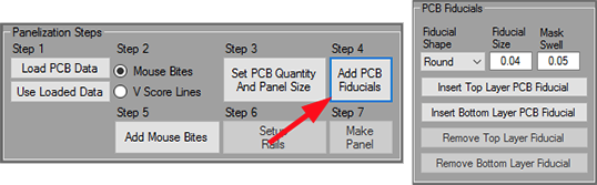
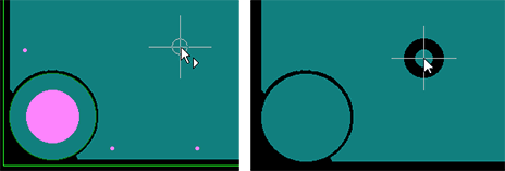
Select either a "Round" (most popular) or "Square" shape from the "Fiducial Shape" combo box. Enter a "Fiducial Size" (determines size of copper pad added) and "Mask Swell" (determines solder mask swell). Then, click on either the "Insert Top Layer PCB Fiducial" or "Insert Bottom Layer PCB Fiducial" button to insert the fiducial. Move the cursor to the location where you want to enter the PCB fiducial and click on "Enter". Note that the Single Design Panelizer will automatically create a clearance if you are inserting the fiducial into a copper plane area on your board.
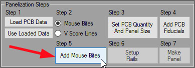
Step 5 - Add Mouse Bites
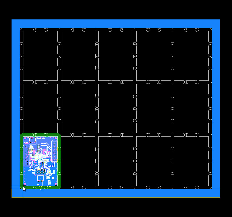
If you chose the "Mouse Bites" option in step 2, then click on the "Add Mouse Bites" button.
This will launch the "Edit Mouse Bites" dialog. You can add mouse bites in one of three ways; "Closest to Click Location", "Center on Edge" or "Distribute on Edge".
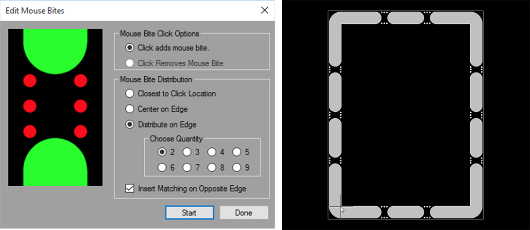
Click "Start" to begin installing the mouse bites. Then click where you want to enter the mouse bites. If desired, click on the opposite edge of the PCB to insert a matching mouse bite on the opposed edge of the PCB. Click "Start" again if you want to insert additional mouse bites. When you’re finished, click "Done". The mouse bites for your entire array will be quickly generated and inserted into your panel.
Step 5 - Add V Score Lines
If you chose the "Mouse Bites" option in step 2, then click on the "Add Mouse Bites" button.
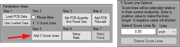
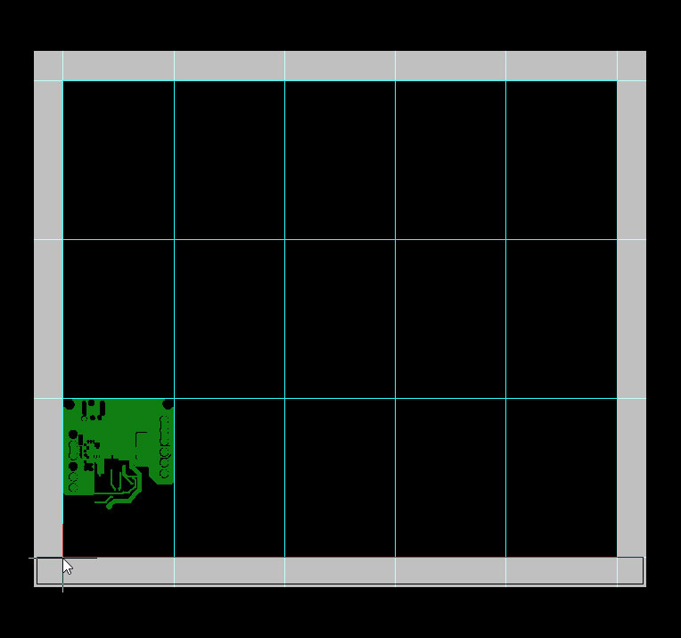
The V Score Lines are added to the panel:
Step 6 - Setup Rails
Click on "Setup Rails" to display the "Rail Options" controls.
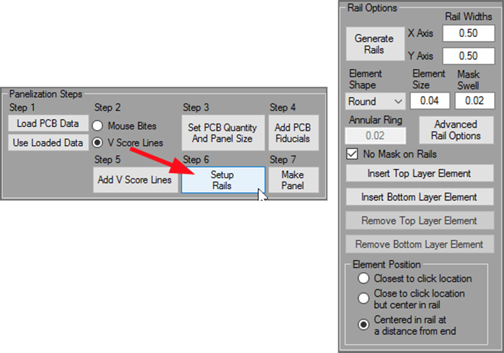
corners of the panel. We also suggest that you offset the distance from the edge of the panel to guard against inadvertently placing a rotated panel into the pick and place machine.
Step 7 - Make Panel
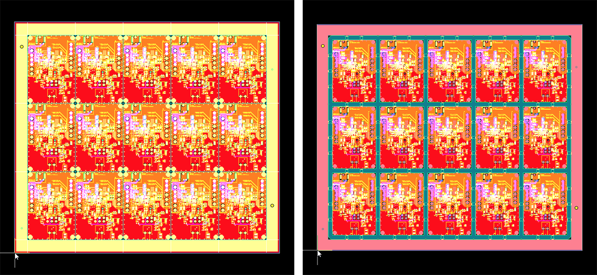
The PCB Analyzer automatically configures your layer numbering so that you can quickly Click on "Make Panel" to create the finished array. A finished panel using V Score Lines is shown on the left. A finished panel using mouse bites is shown on the right.