PCB Concepts

Printed Circuit Board Surface Finishes: A Comparison Guide

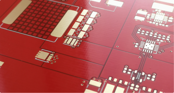
When it comes to printed circuit board (PCB) manufacturing, choosing the right surface finish is essential for ensuring optimal performance, reliability, and solderability. The surface finish not only protects the copper traces from oxidation and corrosion but also provides a solderable surface for component attachment. In this article, we will explore and compare some popular PCB surface finishes, their characteristics, advantages, and limitations, to help you make informed decisions for
Materials used in printed circuit board substrates

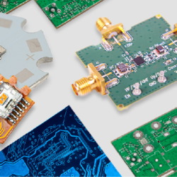
Printed circuit board (PCB) substrate materials are the base layers that make up the PCB. They are typically made of a combination of insulating materials (e.g. fiberglass or plastic) that provide mechanical support, electrical connectivity, and insulation. Common PCB substrate materials include: FR-4 (fiberglass-reinforced epoxy resin) Polyimide Rogers (polymer-ceramic composites) Aluminum The choice of substrate material depends on factors such as electrical performance, thermal resistance, and cost.   FR4 FR4

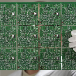
What is PCB Panelization?

Printed Circuit Board assembly using automated equipment such as pick & place machines, stencil printers and reflow ovens provides higher efficiency than manual methods. It is a great option for prototype pcb assembly and low volume production, and the only viable option for high volume production. But automated PCB assembly imposes certain requirements that need to be met when designing and manufacturing a printed circuit board. An important part of

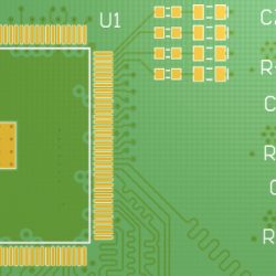
Bulletproof Your PCB Footprint Design

An important part of the PCB design process is creating the footprints. Tiny mistakes during this stage may result in a failed design, no matter how clean and perfect your layout is. And the bad news is that is very easy to make mistakes during footprint creation if you don’t pay enough attention to what you are doing. That’s why you must include some degree of verification process to your

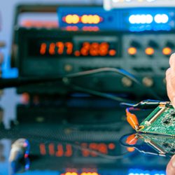
Prototype Printed Circuit Boards:

Imagine this situation: you had a great idea for a new electronic device or product, you have finished your schematic and completed the layout of your Printed Circuit Board (PCB). Now it’s time to send it to the manufacturer. No matter how good you are at electrical engineering or PCB design, you should always make a small batch of prototype PCBs before proceeding with a production order. But what is

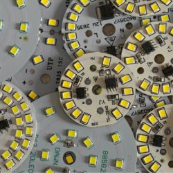
What to consider when designing LED Printed Circuit Boards (PCBs)

Light Emitting Diodes (LEDs) are very popular these days. You can find LED arrays in a variety of products such as gaming, lighting, home decoration, or even in industrial human machine interfaces, just to name a few. Most LED products contain a Printed Circuit Board with LEDs and a built-in control logic circuit. Sometimes the control logic circuitry may reside on a separate board that connects to the LED PCB

Flex & Rigid Flex PCBs

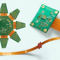
Flexible circuits, also known as flex PCBs, are printed circuit boards that can be bent, twisted and folded because they have a substrate of flexible polyimide film and one or more thin layers of metallic material (usually copper). The copper layers are chemically etched to produce the desired circuit patterns. Adhesive is commonly used to bond the copper to the polyimide film, but other types of bonding can be used.

Blind and Buried Vias

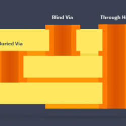
A via (also known as vertical interconnect access) is a copper plated hole that allows electrical connection between layers of a printed circuit board. The hole can be made using a drill or laser. A via consists of a barrel, a pad, and an anti-pad. Through-Hole Vias A through-hole via is a copper plated hole that traverses the entire printed circuit board from one top to bottom. It forms a